Calm · Inspiring · Friendly
Free Desktop Wallpaper for Windows & Mac
5,000+ hand-curated HD & 4K nature, travel, and wildlife photos — free to download and set as your desktop background in one click.
Why Webshots
Modern, calming visuals with simple setup—made for people who love beautiful desktops.
5000+ Photos
Access our vast library of high-resolution photos from around the world.
Easy Desktop App
Simple application for setting wallpapers, screen savers, and playlists.
Smart Screen Savers
Beautiful screen saver settings with dramatic viewing options.
Custom Playlists
Group photos by season, activity, or create your own collections.
Loved by millions
"I get to travel to a different part of the world every day."
I have enjoyed the pictures for the last 10+ years.
Great photos and easy to use!
I get to travel to a different part of the world every day!
Start free, upgrade anytime
Try our free starter collection, then unlock the full library when you're ready.
Free
50+ free wallpapers to start
- Starter collection access
- Full screensaver
- Wallpaper rotation
Premium Monthly
Cancel anytime
- Full photo library — 5,000+ photos
- Smart rotation & playlists
- Advanced screensavers
- Priority support
Premium Yearly
Save 17% vs monthly
- Everything in Monthly
- Like having 2 months free
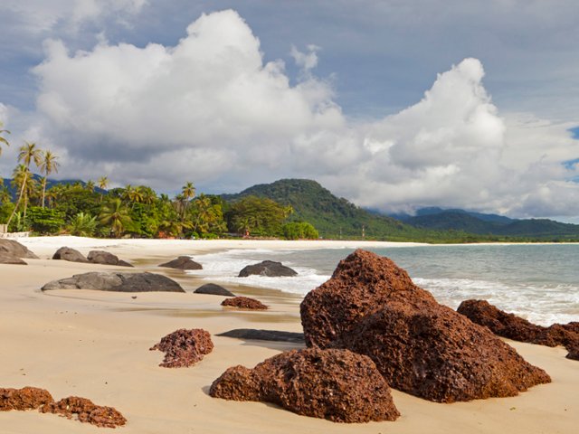
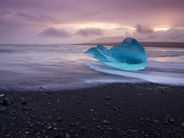
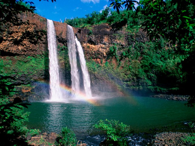
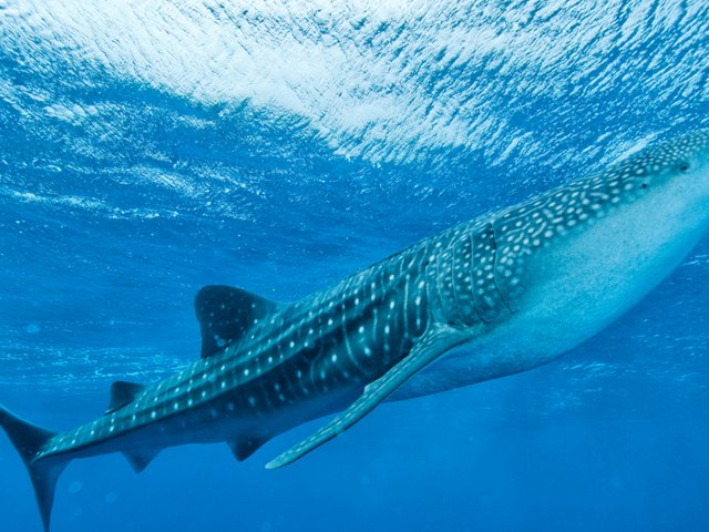
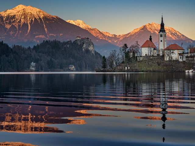
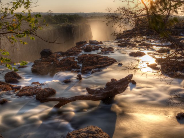
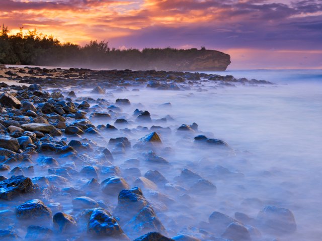
Latest collections
A hand-picked selection to get you started.


Need help?
Visit our support centre or check our FAQs for quick answers.